Sealless Pumps for a Safer and Greener World

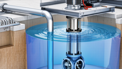
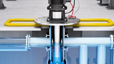
A vertical pump moves liquid through a vertically arranged shaft and casing, often drawing from a sump, tank, well, or deep basin. Its motor sits above the liquid, while the pumping elements extend below the mounting surface. That layout can save floor space and reach submerged liquid. It is useful, but not automatically the right choice.
The U.S. Department of Energy’s Improving Pumping System Performance sourcebook reports that pumping systems use nearly 20% of the world’s electrical energy. That figure covers pumping systems broadly, not vertical pumps alone—a distinction worth keeping clear. Hydraulic Institute guidance also emphasizes selecting pumps around operating conditions, including flow, head, and the fluid being handled. Pump engineer Lev Nelik’s practical selection principle can be paraphrased this way: “Choose for the system, not the label.” The wording here is a paraphrase, not a verified verbatim quotation.
Common vertical pump types include vertical turbine, inline, sump, and submersible designs. A vertical turbine pump may draw water from a deep well; a sump pump handles liquid collected below floor level. Inline models fit into a vertical pipeline, while submersible units operate underwater. The categories can overlap in everyday usage, so specifications matter more than names. Check the required flow, discharge pressure, liquid temperature, solids content, and available installation depth. A compact footprint looks appealing. But installation access, vibration, and maintenance clearance still matter. Pump selection is not tidy work; real sites rarely match a catalog diagram.
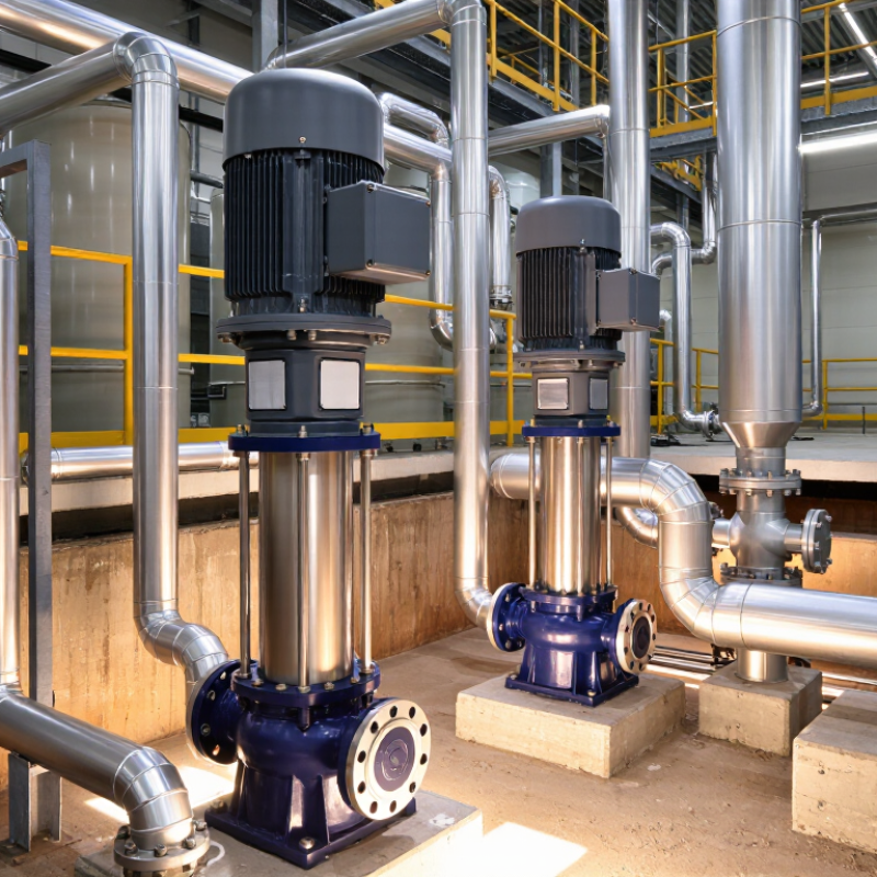
A vertical pump places its shaft upright, with the driver commonly mounted above the pump. This arrangement can save floor space and, in some designs, lift liquid from a sump or well. The exact layout varies: a vertical inline pump handles pipe flow differently from a deep-well turbine pump. The name describes orientation, not one fixed design.
In a vertical turbine pump, liquid enters through a suction bell and reaches the impeller. The impeller adds energy, while diffuser passages guide the flow upward through the pump bowl. From there, liquid travels through the column pipe to the discharge head. It sounds simple. In practice, small changes in clearance or alignment can affect performance.
Key components include the motor, shaft, bearings, impellers, bowls, column, and discharge head. The shaft transfers rotation down to the impellers, so its length and support matter. Bearings help control movement; seals or packing limit leakage where the design requires them. A long shaft can seem straightforward on a drawing, but installation and maintenance deserve careful attention. I would not assume every vertical pump can run partly submerged: the permitted operating level depends on its design and maker’s instructions.
Inside a vertical pump, the rotating impeller transfers energy to the liquid. Curved vanes guide water outward from the impeller eye. Its velocity rises, then the casing or diffuser slows the flow and converts some velocity into pressure head. The result depends on impeller geometry, speed, flow rate, and the liquid being pumped. You can often hear or feel rough operation when inlet conditions become poor. But sound alone is not a reliable diagnosis.
NPSH₃ describes the net positive suction head at which cavitation has reduced a pump’s head by 3% during testing. It is not the point where cavitation first begins. The system’s available NPSH must exceed the pump’s NPSH₃ at the actual operating flow, with a suitable margin. In a vertical installation, liquid level, temperature, suction losses, and submergence all affect that available head. A warm liquid or a falling sump level can narrow the margin quickly. Small details matter. Pump curves provide a useful starting point, but real piping and changing liquid levels can complicate the picture. Field readings are sometimes imperfect, so operating conditions should be checked carefully.
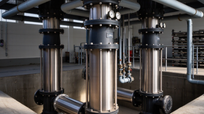
API 610 classifies vertical pumps from VS1 through VS7 by casing arrangement and hydraulic design. The code is more than a naming system: each configuration suits different installation and operating conditions. VS1 uses a suspended, single casing with diffuser hydraulics; VS2 uses a volute. VS3 is an in-line design, often selected where piping layout and limited floor space matter.
VS4 and VS5 are sump arrangements. VS4 uses a cantilever shaft, while VS5 uses a line shaft with submerged bearings. That difference affects bearing lubrication, maintenance access, and tolerance for debris in the liquid. VS6 is a double-casing diffuser pump; VS7 is double-casing with a volute. Double casing can support demanding services, but it also adds design and maintenance considerations. Fit matters.
For example, a deep wet well may point toward VS5, while a compact process line may favor VS3. The choice still depends on liquid properties, required head and flow, submergence, and site access. API 610 type alone cannot confirm suitability. Check the applicable edition and project specification, then review the pump curve and installation details. The classifications are useful, but real installations rarely fit a label perfectly.
A vertical turbine pump places its bowl assembly below the liquid level, with a column carrying water to the surface. Inside the bowls, impellers add energy to the flow. Multiple bowl stages are arranged in series: head increases with each stage, while flow remains broadly similar. Actual performance depends on losses and operating conditions.
Specific speed helps compare impeller designs at a pump’s best-efficiency point. It is calculated as Ns = n√Q/H^0.75, using consistent units and per-stage head. Lower values generally indicate more radial-flow designs; higher values indicate mixed or axial flow. Small details matter. Check the manufacturer’s stated convention, since unit choices change the numerical value. Bowl-stage count should follow required head, not a rule of thumb alone.
Duty selection starts with flow and total dynamic head, then accounts for changing water levels, column losses, solids, and available submergence. The U.S. Department of Energy’s 2006 Improving Pumping System Performance sourcebook reports that pumping systems use nearly 20% of global electricity demand; in some industrial operations, they consume 25–50% of energy. Those figures describe pumping broadly, not vertical turbines specifically. Still, they show why matching the duty point matters. That assumption deserves checking: a pump may run, yet spend much of its life away from its efficient range.
| Topic | Dimension or Type | Description and Practical Data | Design or Duty Implication |
|---|---|---|---|
| Vertical turbine pump | Basic arrangement | A vertical pump with one or more impellers in submerged bowl assemblies, connected by a vertical shaft to a driver above the liquid. | Often used where the liquid source is below grade, such as a well, wet pit, reservoir, or sump. |
| Pump construction | Common components | The main assembly typically includes a discharge head, column pipe, line shaft, and one or more bowl assemblies containing impellers and diffusers. | The bowl assembly develops head; the column supports the shaft and conveys liquid to the discharge head. |
| Bowl-stage arrangement | Single-stage | One impeller and bowl assembly produce the pump’s developed head. | Suitable when one stage can meet the required head at the specified flow and operating speed. |
| Bowl-stage arrangement | Multistage | Two or more bowl stages are arranged in series. At a given flow, their developed heads are approximately additive. | For example, four stages developing about 100 ft of head each provide roughly 400 ft of total pump head, subject to actual selection and losses. |
| Impeller flow type | Radial-flow | Liquid leaves the impeller mainly in a radial direction. Radial-flow designs generally suit lower specific-speed applications. | Commonly selected for relatively higher head per stage and lower-to-moderate flow, depending on the design. |
| Impeller flow type | Mixed-flow | Liquid leaves the impeller with both radial and axial velocity components. | Often used for intermediate combinations of flow and head per stage. |
| Impeller flow type | Axial-flow | Liquid moves predominantly parallel to the pump shaft through the impeller. | Typically suited to high-flow, low-head-per-stage duties; the appropriate design depends on the full pump curve and system requirements. |
| Specific speed | US customary convention | Ns = N × √Q ÷ Hs0.75, where N is speed in rpm, Q is flow in US gpm at the best-efficiency point, and Hs is head per stage in feet at that point. | Specific speed is a dimensionless index only when a consistent unit convention is used; values calculated with metric units are not directly comparable to US customary values. |
| Specific-speed guidance | Approximate impeller families | Under the US customary convention, radial-flow designs are often associated with lower Ns values, mixed-flow designs with intermediate values, and axial-flow designs with higher values. The ranges overlap and vary by reference and design. | Use specific speed as a preliminary classification aid, not as a substitute for the manufacturer’s certified performance curve or a complete hydraulic selection. |
| Illustrative duty | Four-stage example | At 1,800 rpm, 500 gpm, and 100 ft of head per stage, the US customary specific speed is approximately 1,270. Four stages at that stage head would provide about 400 ft of pump head. | This is an illustrative calculation, not a recommended selection. Actual flow, head, efficiency, power, submergence, and operating limits must be checked against the selected pump curve. |
| Duty-point selection | Flow and total dynamic head | Define the required flow and total dynamic head, including static lift, pressure requirements, and friction losses in the system. | The selected pump should operate near its best-efficiency region over the expected operating range, not merely meet a single nominal point. |
| Installation considerations | Liquid level and materials | Check minimum submergence, available well or sump dimensions, liquid temperature, solids, corrosion, and the required shaft and bearing arrangement. | These factors affect hydraulic performance, vibration risk, material suitability, reliability, and whether the pump can be installed and maintained safely. |
| Important note | Performance verification | Stage head, flow capacity, efficiency, and allowable operating range depend on the specific bowl and impeller geometry, speed, and liquid properties. | Confirm final selection using a pump performance curve and project-specific system data. |
A vertical pump places its shaft upright, often with the hydraulic bowl assembly below the motor or discharge head. Selection starts with the duty point: required flow and total head, not a catalog’s maximum figures. Build a system curve from static lift, pipe friction, and pressure requirements. Then check the full operating range, since a pump may meet peak demand yet run poorly at normal demand.
Not just peak flow.
NPSH needs equal care. Compare available NPSH in the installation with the pump’s required NPSH at the selected flow, and apply a suitable margin. ANSI/HI 9.6.1 provides guidance on NPSH margin; suction conditions can change with liquid temperature, elevation, and intake geometry. A tidy calculation can still miss a real-world swirl or obstruction.
The Hydraulic Institute’s ANSI/HI 14.6 standard sets procedures for rotodynamic pump performance acceptance tests, including flow, head, and power measurements. Specify the test grade and acceptance criteria in advance, rather than treating a test curve as a guarantee for every installation. The U.S. Department of Energy’s Improving Pumping System Performance sourcebook also emphasizes matching pump operation to system demand.
Field data may disagree with the model. That is worth investigating.