Sealless Pumps for a Safer and Greener World

Choosing a vertical pump in 2026 requires more than comparing catalog prices. It demands a clear reading of the entire pumping system. The U.S. Department of Energy identifies pumping systems as major industrial energy users. Its Pumping System Assessment Tool emphasizes system efficiency, operating points, and avoidable losses. Market studies from Grand View Research and MarketsandMarkets also show continued demand for pumps in municipal water, power generation, agriculture, and process industries. However, their market boundaries differ. Their figures should not be treated as identical facts.
“ The pump is only one part of the pumping system,” says Dr. Lev Nelik, a pump-system consultant and author of Centrifugal and Rotary Pumps. That principle matters when selecting a vertical pump. Start with flow, total dynamic head, fluid temperature, viscosity, solids content, and available installation depth. Then check NPSH, column length, shaft stability, bowl efficiency, motor loading, and maintenance access. A wet well may look spacious, yet a few centimeters of clearance can affect vibration and service work.
Do not trust a single efficiency number. Ask for the performance curve at your real operating point. Review minimum flow, transient conditions, seal design, metallurgy, and spare-part availability. A stainless-steel bowl may resist corrosion, but it will not solve poor hydraulic sizing. That sounds simple. It is not. Field experience often exposes assumptions hidden inside clean spreadsheets. The best choice balances purchase cost, energy consumption, downtime risk, and the operator’s actual working conditions. A useful decision remains open to correction after commissioning, because real water levels, sediment, and seasonal demand rarely behave perfectly.
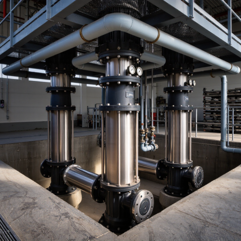
Choosing a vertical pump starts with the application, not the catalog. Define the liquid, flow rate, total dynamic head, temperature, viscosity, and solids content. A wastewater basin needs different protection than a clear-water cooling loop. Record the operating range, not only the best-case duty point. Pumping systems can represent nearly 25% of industrial electricity use, according to the U.S. Department of Energy’s Improving Pumping System Performance guide. Small efficiency losses can become expensive over long operating hours.
Check suction conditions carefully. Measure the available NPSH and compare it with the pump’s required NPSH, including a safety margin. Confirm the tank depth, minimum liquid level, pipe length, valve losses, and discharge pressure. Vertical designs may save floor space, but their column length, shaft alignment, vibration, and maintenance access need practical review. ISO 5199 and Hydraulic Institute guidance emphasize reliable testing, performance tolerances, and suitable installation conditions. A neat specification is not always a correct one. Field measurements may be incomplete.
Tips: Write a duty table with normal, minimum, and maximum conditions. Ask whether solids can settle around the suction inlet. Consider variable-speed control when demand changes frequently, since throttling can waste energy. Check materials against corrosion and temperature, then verify seal access and lifting requirements. Leave room for doubt. A conservative selection is often safer than an optimistic one. Sources: U.S. Department of Energy, Improving Pumping System Performance; ISO 5199; Hydraulic Institute engineering guidance.
Use this practical selection matrix to define the duty point, installation conditions, fluid properties, materials, and control requirements before specifying a vertical pump.
| Application | Typical Flow Range | Typical Head Range | Fluid and Temperature | Recommended Vertical Pump Arrangement | Key Materials and Construction | Critical Selection Requirements |
|---|---|---|---|---|---|---|
| Water Supply and Pressure Boosting | 10–500 m³/h | 30–250 m | Clean water, generally 5–40°C; suspended solids should normally remain very low. | Vertical multistage pump with a closed or semi-open impeller, installed on a baseplate or in-line configuration. | Stainless steel or coated carbon steel wetted parts; mechanical seal selected for the water chemistry. | Confirm the duty point, available NPSH, minimum flow, motor power, and required pressure stability. A variable-frequency drive can improve part-load efficiency. |
| Cooling Water Circulation | 50–2,000 m³/h | 15–120 m | Fresh water, treated process water, or cooling-tower water; commonly 10–45°C. | Vertical long-shaft, vertical turbine, or vertical inline pump, depending on sump depth and suction conditions. | Corrosion-resistant impellers and shaft materials; coatings may be required for treated or contaminated cooling water. | Evaluate continuous-duty operation, temperature rise, corrosion allowance, vibration, shaft stiffness, and the effect of cooling-system fouling on system resistance. |
| Deep-Well or Raw-Water Intake | 20–1,500 m³/h | 40–300 m | Raw water with possible sand, silt, or biological content; typically 5–35°C. | Vertical turbine pump with multiple bowl stages and a submersed suction bell or well installation. | Cast iron, bronze, stainless steel, or engineered coatings selected according to water quality and sand content. | Define well diameter, static and drawdown levels, submergence, sand concentration, column length, line-shaft lubrication, and allowable starting frequency. |
| Municipal Wastewater and Drainage | 50–3,000 m³/h | 10–100 m | Wastewater containing suspended solids, fibers, or debris; commonly 5–40°C. | Vertical non-clog, mixed-flow, or axial-flow pump with an open suction arrangement. | Wear-resistant cast iron, stainless steel, or duplex components; shaft sealing and impeller clearance must suit solids loading. | Specify solids size, ragging risk, dry-well or wet-well layout, minimum submergence, anti-vortex provisions, cleanout access, and clog-resistant impeller design. |
| Flood Control and Stormwater | 500–20,000 m³/h | 3–35 m | Stormwater, river water, or drainage water; normally 0–35°C with variable solids content. | Vertical axial-flow or mixed-flow pump optimized for high flow and low-to-medium head. | Coated cast iron, stainless steel, or corrosion-resistant alloys; intake screens and debris-handling features may be necessary. | Prioritize hydraulic efficiency, debris passage, intake velocity, vortex prevention, emergency operation, motor starting method, and resistance to intermittent duty. |
| Boiler Feed and High-Pressure Process Water | 10–400 m³/h | 100–600 m | Deaerated or treated water; commonly 80–180°C, depending on the process and pump arrangement. | Vertical multistage or vertical barrel-type pump designed for elevated pressure and temperature. | Heat-resistant alloy steel or stainless steel; mechanical seals and gaskets must be rated for the specified temperature and pressure. | Calculate NPSH available at operating temperature, check flashing risk, specify warm-up requirements, and verify pressure containment, shaft thrust, and minimum-flow protection. |
| Chemical Transfer and Dosing Systems | 0.1–100 m³/h | 10–150 m | Acids, alkalis, solvents, or chemical solutions; temperature may range from 0–120°C. | Vertical sealless, magnetic-drive, canned-motor, or vertical cantilever pump when leakage control is critical. | Material selection may include fluoropolymers, high-alloy stainless steel, ceramic, or other chemically compatible materials. | Confirm chemical compatibility, concentration, viscosity, vapor pressure, seal strategy, containment requirements, hazardous-area classification, and dry-run tolerance. |
| Hot Oil and Thermal-Fluid Circulation | 5–300 m³/h | 20–180 m | Thermal oil or heat-transfer fluid; commonly 100–350°C, depending on the fluid specification. | Vertical cantilever or vertical process pump with a high-temperature seal and suitable bearing arrangement. | Heat-resistant carbon steel or alloy components; seal faces, elastomers, and bearings must match the thermal-fluid temperature. | Check fluid viscosity at start-up, vapor pressure, thermal expansion, seal cooling, shaft alignment, insulation requirements, and allowable pump casing temperature. |
| Mining Slurry and Abrasive Liquids | 20–1,000 m³/h | 15–150 m | Slurry containing mineral solids; solids concentration and particle size can vary widely. | Vertical cantilever sump pump or vertical slurry pump with an open impeller and replaceable wear components. | High-chrome alloy, rubber-lined, or other abrasion-resistant wetted parts selected according to particle size and chemistry. | Define solids concentration by mass or volume, particle size, slurry density, settling behavior, corrosion rate, wear allowance, and required service life. |
| Fire Protection Water Systems | 100–1,000 m³/h | 40–180 m | Clean or mildly contaminated water; typically 5–40°C. | Vertical turbine or vertical centrifugal fire pump configured for automatic emergency starting. | Durable coated or corrosion-resistant components; construction and controls must meet the applicable local fire code. | Verify rated flow and pressure, churn pressure, suction level, driver type, standby power, automatic start logic, test arrangements, and regulatory approval requirements. |
Selection note: The ranges shown are typical preliminary design values, not guaranteed operating limits. Final pump selection should be based on the complete system curve, duty-point tolerance, NPSH margin, fluid compatibility, motor service factor, applicable codes, and the manufacturer’s certified performance data.
Choosing a vertical pump in 2026 starts with its operating principle, not its catalogue appearance. Vertical turbine pumps use stacked impellers to lift water from deep wells, tanks, or intake structures. Each impeller adds head, making this design suitable for high pressure and large flow rates. Vertical inline pumps place the suction and discharge ports on one axis. They save floor space, but usually fit cleaner fluids and moderate lifting duties. Vertical submersible pumps operate below the liquid surface. Their submerged motor reduces priming problems, although inspection can become slower and more expensive.
The U.S. Department of Energy reports that pumping systems may consume 25% to 50% of industrial motor-system energy. That figure makes efficiency more than a specification. Compare the pump curve with the real duty point, including friction losses and changing demand. Variable-speed control can reduce throttling losses, but it may introduce cooling, vibration, or control issues. The Hydraulic Institute’s standards emphasize tested performance, net positive suction head, and operating limits. Field experience still matters. Sediment can wear impellers faster than a laboratory curve suggests.
Check liquid temperature, solids concentration, corrosion risk, shaft length, and maintenance access. A long vertical shaft may need careful alignment. A compact inline unit may transmit more vibration if the pipework is poorly supported. The International Energy Agency links motor-system efficiency with wider industrial energy savings, yet efficiency numbers are not always comparable. A spreadsheet can still lie. Ask for test conditions, tolerances, and lifecycle energy data. I would also leave a practical margin, but not an oversized one; excessive capacity can force inefficient throttling and unstable operation.
Material selection should follow the fluid, temperature, pressure, and maintenance environment. Stainless steel suits many clean-water duties, while more resistant alloys may be necessary for chloride-rich or abrasive liquids. A small material mistake can become a shutdown. The seal needs equal attention. Mechanical seals reduce leakage, but dry running, misalignment, and poor flushing can shorten their life. Ask for tested seal compatibility, not only a catalogue temperature rating. I have seen promising specifications fail when real solids entered the pump.
Motor efficiency affects operating cost, especially at long duty cycles. The International Energy Agency reports that electric motor systems consume roughly 40% of global electricity. The U.S. Department of Energy also identifies pumping energy as a major lifecycle expense, often exceeding purchase cost. Choose a motor for the actual duty point, not the maximum advertised capacity. Oversizing feels safe. It often wastes energy.
Control systems should match process behavior. Variable-frequency drives can reduce throttling losses, but only when minimum flow, cooling, and motor insulation are properly checked. Pressure sensors, dry-run protection, and alarm history improve practical reliability. IEC 60034-30-1 efficiency classes help compare motors, yet efficiency data alone cannot predict system performance. My own preference is conservative commissioning with measured flow, pressure, and power. The first setting is rarely perfect. Recheck it.
How to Choose a Vertical Pump in 2026?
Calculate Pump Capacity, Head, Efficiency, and NPSH
Selecting a vertical pump starts with the actual duty point, not the largest available motor. Measure the required flow rate, fluid temperature, density, and operating schedule. Capacity, or Q, should match process demand in cubic meters per hour. Add static head, pressure head, and friction losses to calculate total dynamic head. Include losses through valves, elbows, filters, and rising pipe sections. Small details matter.
Use the pump curve to find the intersection between system resistance and pump performance. Calculate hydraulic power with P = ρgQH, then estimate shaft power by dividing it by efficiency. A pump operating near its best efficiency point usually runs more smoothly and consumes less energy. Do not trust a single efficiency value. Fluid viscosity, wear, and changing flow can reduce real performance.
NPSH deserves a separate check. Calculate NPSH available from liquid level, surface pressure, vapor pressure, and suction losses. Keep NPSHa above the manufacturer’s NPSHr with a sensible safety margin. I have seen installations pass a spreadsheet review but cavitate after a warm process changed vapor pressure. That mistake is expensive. Recheck the calculation using the hottest liquid, lowest tank level, and dirtiest expected strainer. Field data can disagree with design assumptions. Measure it when possible.
How to Choose a Vertical Pump in 2026?
When choosing a vertical pump in 2026, treat installation as an operating decision, not a catalog exercise. Measure flow, total dynamic head, fluid temperature, solids, and available lifting space. A pump that fits the sump may still suffer from poor suction conditions. Check NPSH margin, baseplate stiffness, shaft alignment, and access for seal replacement. Leave clearance above the motor. Technicians should not need a crane for every inspection. That happens more often than specifications admit.
Maintenance planning should include vibration checks, lubrication intervals, seal access, spare-part storage, and lockout procedures. Install guards around rotating parts and provide safe platforms for inspection. A small alignment error can create heat, noise, and repeated bearing failures. The U.S. Department of Energy indicates that pumping systems may represent about 20–25% of industrial electricity use. Efficiency deserves attention. Do not select a pump only by purchase price.
The Pump Life Cycle Costs guide from the Hydraulic Institute and Europump estimates that energy can approach 40% of total lifecycle cost, while initial purchase may represent about 10%. Compare power consumption at actual duty points, not only at the best-efficiency point. Include downtime, labor, water damage, and disposal costs. These percentages are useful, but not universal. Dirty fluids, throttled valves, and irregular operation can change the calculation sharply. A spreadsheet may look precise while hiding weak assumptions. Review those assumptions with maintenance staff before approval.
Evaluate installation, maintenance, safety, and lifecycle cost together instead of selecting a pump by purchase price alone.
The chart uses a practical 100-point reference weighting for an engineering review: lifecycle cost and safety receive the highest priority, while installation and maintenance remain essential selection factors. The weighting should be adjusted for site conditions, fluid characteristics, duty cycle, regulatory requirements, and available service resources.