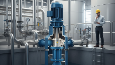
Sealless Pumps for a Safer and Greener World

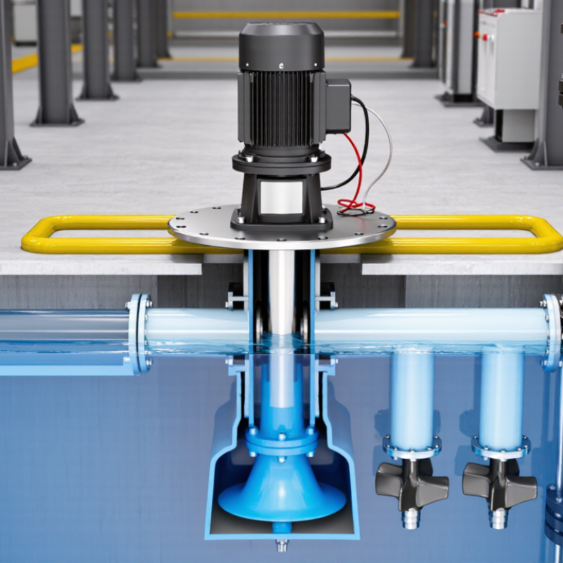
A vertical pump moves liquid through a vertical shaft arrangement, often from a sump, tank, or deep well. Its motor sits above the liquid, while the bowls, impellers, and suction section extend downward. This design saves floor space and can lift water from considerable depths. It also places critical components in different environments, which affects maintenance and reliability.
When the motor starts, it turns the vertical shaft and impellers. Liquid enters through the suction inlet, gains pressure inside the rotating impeller, and rises through the discharge column. In a vertical turbine pump, several impeller stages may work together. Each stage adds pressure. The final flow then reaches a pipeline or distribution system.
Small details matter. A worn bearing may create vibration before the flow drops noticeably. Misalignment can damage seals, shafts, or column bearings. Operators should check vibration, motor current, lubrication, and discharge pressure during routine inspections. Manufacturer data remains essential because pump performance changes with liquid temperature, viscosity, depth, and system resistance.
Not every vertical pump suits every installation. That point is easy to overlook. A pump selected only by flow rate may operate inefficiently or fail early. Engineers usually compare total dynamic head, net positive suction conditions, materials, motor capacity, and expected duty cycles. Field experience helps, but it should not replace documented calculations and local safety procedures. This guide explains the working principle, main components, common designs, and practical selection concerns surrounding a vertical pump. Some installations still expose weaknesses after commissioning, so careful testing and honest review remain necessary.
What Is a Vertical Pump and How Does It Work?
Definition and Basic Purpose of a Vertical Pump
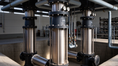
A vertical pump is a mechanical device that moves liquid through a vertically arranged shaft and impeller system. Its motor usually sits above the liquid, while the pumping components extend downward. This layout allows the pump to draw fluid from tanks, wells, sumps, or deep basins.
The basic purpose is simple: lift liquid and maintain a controlled flow. As the motor turns the shaft, the impeller adds energy to the fluid. The liquid enters near the lower section, gains pressure, and travels upward through the discharge passage. Some models use one impeller. Others use several stages for higher pressure.
Vertical pumps are useful where floor space is limited or the liquid level changes significantly. In a working pump room, the arrangement can look practical but demanding. The shaft must stay aligned. Bearings need suitable lubrication. The intake should remain below the liquid surface to avoid air entering the system.
Small details matter.
A blocked screen, worn impeller, or incorrect submergence can reduce performance. I have seen design drawings appear convincing while the actual basin created turbulence near the suction inlet. That mistake is easy to overlook. Pump selection should consider flow rate, lifting height, liquid temperature, viscosity, solids content, and operating hours. A vertical pump is not automatically the best choice for every deep-water application.
A vertical pump lifts liquid through a vertically arranged shaft and casing. Unlike a horizontal pump, its motor usually sits above the discharge head. This layout saves floor space and allows the pump to reach deep tanks, wells, or sumps.
The motor supplies rotary power through a coupling and vertical shaft. The shaft transfers torque to one or more impellers below the liquid level. Each impeller adds velocity and pressure to the flow. Stationary bowl sections then guide the liquid toward the next impeller or the column pipe. The suction bell helps reduce turbulence at the inlet. Small details matter here. Poor inlet conditions can cause vibration, noise, and premature wear.
The discharge head redirects liquid into the outlet pipe. It also supports the shaft assembly and often houses the mechanical seal or packing. Bearings keep the shaft centered as it rotates. Thrust bearings carry the weight of the rotating parts and hydraulic forces. Column bearings support longer shafts between stages. During inspection, technicians check coupling alignment, bearing lubrication, seal leakage, and unusual vibration. A slight vibration is not always harmless. It may indicate imbalance, misalignment, or cavitation. Pump construction varies with flow rate, liquid temperature, depth, and material requirements. That variation makes a simple component checklist useful, but never complete. The manufacturer’s installation data and measured operating conditions should guide final decisions.
What Is a Vertical Pump and How Does It Work?
A vertical pump moves fluid through equipment arranged along a vertical shaft. Its motor sits above the liquid, while the impellers extend downward into the casing. This design saves floor space and suits deep tanks, wells, and sump applications. The process sounds simple, yet field conditions often disagree.
Fluid enters through the suction opening at the lower end. When the motor starts, it turns the shaft and connected impellers. Each impeller adds velocity to the fluid. Stationary diffuser passages then convert part of that velocity into pressure. The pressurized fluid rises through the discharge column. Guides inside the column help control movement and reduce unwanted swirling. At the surface, the outlet directs fluid toward piping or another process stage.
Vertical pumps depend on correct submergence, alignment, and lubrication. If the liquid level drops too far, the pump may draw air and vibrate. That vibration can damage bearings, seals, or the shaft. Poor alignment creates uneven loading, even when flow appears normal. Operators should check noise, vibration, temperature, and discharge pressure during operation. A gradual pressure decline may indicate wear, blockage, or changing fluid conditions. It is tempting to blame the impeller immediately, but that assumption can waste time. The real cause may be a clogged screen or a leaking connection. Exact performance also depends on fluid viscosity, temperature, and pump geometry.
A vertical pump lifts fluid through an impeller and vertical column. The impeller converts mechanical energy into fluid pressure, while the column guides the flow upward to the discharge point.
This representative profile shows pressure increasing rapidly across the impeller and then declining slightly through the vertical column and outlet piping because of elevation and friction losses. Approximately 1 bar of pressure corresponds to about 10 metres of water head.
A vertical pump moves liquid through a vertically arranged shaft and casing. Its motor sits above the liquid, while the pumping elements extend downward. This design saves floor space and suits deep tanks, wells, and sumps. As the impeller rotates, it creates pressure and guides fluid toward the discharge line. Shaft length, bearing support, and submergence depth affect stability.
Vertical pumps come in several practical forms.
Vertical turbine pumps lift water from deep wells, reservoirs, and irrigation systems. Their stacked bowl assemblies can handle considerable lift.
Vertical mixed-flow pumps move large volumes at moderate pressure, making them useful for drainage, flood control, and cooling-water circulation.
Vertical inline pumps fit directly into piping systems. They often serve building services, process circulation, and heating systems.
Vertical sump pumps handle liquid collected in pits. Some models manage solids, but their clearances need careful checking.
Applications often determine the pump type more than motor power does. A wastewater sump may require corrosion-resistant materials and a debris-tolerant impeller. A cooling circuit may value steady flow and compact installation. In field inspections, unusual vibration often points to poor alignment, worn bearings, or insufficient submergence. Small installation errors matter. The boundary is not always tidy. A pump selected from flow figures alone may perform poorly when liquid viscosity, temperature, or suspended solids change. Engineers should verify the duty point, liquid properties, operating depth, maintenance access, and emergency conditions before approval.
A vertical pump places its motor above the liquid and guides power through a vertical shaft. Impellers sit below the surface, often inside bowl assemblies or submerged casing. As the shaft rotates, the impellers raise pressure and move water upward through the discharge column. This layout suits deep wells, cooling-water intakes, and narrow sumps.
Its footprint is small. That matters where floor space is limited. The motor also stays away from hot, dirty, or corrosive liquids. However, vertical designs need careful shaft alignment and strong structural support. Long shafts can amplify vibration. Installation may require lifting equipment and deeper access than expected. Maintenance is not always simple.
Efficiency deserves close attention. The U.S. Department of Energy reports that pumping systems can consume 25–50% of industrial facility electricity. Its industry sourcebook also identifies potential energy savings of 20–50% through system improvements. These figures make selection more important than purchasing efficiency alone. Engineers should match the pump to flow, total head, fluid temperature, solids content, and required operating hours. Check NPSH available, column length, motor loading, and the best-efficiency region. Hydraulic Institute guidance supports evaluating the full operating range, not one duty point. A pump may perform well on paper but struggle during seasonal demand. That is an easy mistake. Field measurements, including pressure, flow, vibration, and power, can reveal it.