Sealless Pumps for a Safer and Greener World

ISO pumps are standardized process pumps designed for predictable performance, interchangeability, and safer maintenance. They commonly follow ISO 2858 dimensions and ISO 5199 technical requirements. These standards cover hydraulic performance, construction, testing, and installation expectations. In practical terms, an ISO pump converts motor power into fluid movement through a rotating impeller. The impeller creates velocity. The casing then converts part of that velocity into pressure.
The market context is substantial. Grand View Research estimated the global industrial pumps market at approximately USD 69.7 billion in 2023. Its report also projects continued growth through 2030, driven by water treatment, chemicals, energy, and manufacturing. The U.S. Department of Energy notes that pumping systems may consume 25% to 50% of electricity in some industrial facilities. That figure makes pump selection more than a purchasing decision. It becomes an energy and reliability decision.
Dr. Heinz P. Bloch, a recognized rotating-equipment authority, offers a useful warning: “A pump is only as reliable as its installation.” The statement deserves careful thought. Even a correctly specified iso pumps unit can suffer from cavitation, seal damage, vibration, or premature bearing failure. Poor alignment leaves visible clues, such as hot couplings and leaking mechanical seals. This article explains how iso pumps work, how their parts interact, and where operating mistakes begin. Some applications remain difficult to predict. Real fluid properties, pipe layouts, and maintenance habits can change the result. That uncertainty should encourage measurement, not assumptions.
What Are ISO Pumps and How Do They Work?
ISO pumps are usually standardized centrifugal pumps used for transferring liquids in industrial systems. The term describes a design framework, not a single pump model. ISO 2858 commonly defines key dimensions, such as capacity, head, and mounting measurements. ISO 5199 adds technical requirements for many process pumps. Always check the applicable standard and edition.
Their operation is straightforward. A motor rotates an impeller inside the casing. Liquid enters near the impeller center, gains velocity, and moves toward the outer casing. The casing then converts much of that velocity into pressure. In a chemical plant, for example, the pump may move clear water through a pipe while handling temperatures and pressures specified by the process design.
What makes ISO pumps different is interchangeability. Standardized dimensions can simplify replacement, installation, and maintenance. A correctly selected replacement may fit existing pipework and baseplate arrangements with fewer modifications. That can reduce downtime, but it is not automatic. Shaft seals, materials, motor power, rotation direction, and operating limits still require careful checking. A pump that fits physically may perform poorly with abrasive liquid, excessive viscosity, or low suction pressure. This detail is often overlooked. Field measurements and the latest technical documentation matter more than a familiar label.
ISO pumps are centrifugal pumps designed around internationally recognized dimensions, performance requirements, and testing practices. The term does not describe one single pump model. It identifies a design family that supports interchangeability and consistent engineering decisions. Common references include ISO standards covering dimensions, technical specifications, and acceptance testing.
Their classification begins with construction. An ISO pump may have a horizontal or vertical shaft, an end-suction or split-case arrangement, and one or several impeller stages. Single-stage units suit many transfer duties, while multistage designs create higher pressure. Engineers also classify pumps by impeller type, casing structure, sealing method, and installation position. Closed impellers often serve clean liquids. Open or semi-open designs may handle liquids with limited solids.
Selection depends on more than flow rate. Engineers check pressure, temperature, viscosity, material compatibility, and net positive suction head. Shaft alignment matters during installation. Even a small pipe strain can increase vibration near the coupling. In the field, technicians may inspect bearing temperature, mechanical seal leakage, and sound changes during operation. These details reveal problems that a catalog curve cannot show.
Classification is not always perfectly neat. A pump can fit several categories at once. That is why the duty point and operating environment must guide the final choice. A technically compliant pump may still perform poorly if it runs far from its best efficiency point. Careful commissioning remains essential.
| Data Dimension | Classification or Feature | Design and Operating Description | Relevant Technical Information |
|---|---|---|---|
| Definition | ISO-compliant centrifugal pump | An industrial pump designed, manufactured, or tested in accordance with one or more applicable International Organization for Standardization requirements. | “ISO pump” is a general industry term rather than the name of one single pump design. The applicable standard depends on the service and pump type. |
| Primary pump principle | Dynamic centrifugal pumping | A rotating impeller transfers mechanical energy from the driver to the liquid, increasing fluid velocity. The casing then converts part of that velocity into pressure. | Flow is generally continuous while the pump is operating and depends on speed, impeller diameter, system resistance, and fluid properties. |
| Typical hydraulic arrangement | End-suction, single-stage, overhung impeller | The suction nozzle is usually located axially at the front of the casing, while the discharge nozzle is commonly arranged radially or vertically upward. | This configuration is widely associated with the dimensional series covered by ISO 2858, although not every ISO-compliant pump has this arrangement. |
| Stage classification | Single-stage or multistage | A single-stage pump uses one impeller. A multistage pump uses several impellers in series, with the discharge pressure increasing across each stage. | Multistage designs are selected when higher head is required without relying on one very large impeller. |
| Shaft and impeller position | Overhung or between-bearings | In an overhung design, the impeller is mounted beyond the last bearing. In a between-bearings design, bearings support the shaft on both sides of the hydraulic assembly. | Overhung pumps are common for general process services; between-bearings designs are used where larger loads, higher power, or greater rotor support are required. |
| Casing design | Volute or diffuser casing | A volute gradually increases flow area around the impeller. A diffuser uses stationary vanes to reduce velocity and recover pressure. | Volute casings are common in general-purpose pumps, while diffuser arrangements are often used in multistage or high-head applications. |
| Impeller classification | Closed, semi-open, or open | Closed impellers have shrouds on both sides, semi-open impellers have one shroud, and open impellers have no full shroud. | Closed impellers generally provide higher hydraulic efficiency with clean liquids; open or semi-open designs can better tolerate solids but may have lower efficiency. |
| Shaft orientation | Horizontal or vertical | Horizontal pumps usually place the shaft parallel to the foundation. Vertical pumps place the shaft perpendicular to the foundation and may use a submerged or extended hydraulic assembly. | Orientation is selected according to available space, suction conditions, tank geometry, maintenance access, and installation requirements. |
| Drive arrangement | Direct-coupled or separately coupled | The driver may connect directly through a flexible coupling or operate through another transmission arrangement. A motor is the most common driver for industrial centrifugal pumps. | Driver selection must match pump speed, absorbed power, starting conditions, hazardous-area requirements, and the operating point. |
| Shaft sealing | Mechanical seal or packed gland | A mechanical seal uses controlled contact between stationary and rotating faces. Packing uses rings compressed around the shaft or sleeve. | Seal selection depends on pressure, temperature, fluid compatibility, emissions control, solids content, and dry-running risk. |
| Common wetted materials | Metallic or corrosion-resistant construction | Typical material families include cast iron, carbon steel, stainless steel, duplex stainless steel, and engineered alloys. | The material must be compatible with the pumped liquid, concentration, temperature, erosion rate, and corrosion mechanism. |
| Performance classification | Flow, head, efficiency, power, and speed | The operating point is defined by required flow rate and total dynamic head. Efficiency and absorbed power indicate the energy needed to achieve that duty. | Pump performance is normally evaluated using characteristic curves and verified through hydraulic performance testing. |
| Operating range | Best efficiency point and allowable operating region | The best efficiency point is the flow at which hydraulic efficiency is typically highest. Operation far from this point can increase vibration, recirculation, radial thrust, and seal or bearing loads. | The acceptable range is pump-specific and should be established from the manufacturer’s performance data and applicable project requirements. |
| Cavitation consideration | Net positive suction head | The available net positive suction head must exceed the pump’s required value by an appropriate margin to reduce the risk of vapor-bubble formation and collapse. | NPSH depends on liquid vapor pressure, suction pressure, temperature, elevation, flow rate, and suction-line losses. |
| Dimensional standard | ISO 2858 | Defines a basic dimensional and operating classification for certain end-suction centrifugal pumps with horizontal axial suction and radial discharge. | It addresses standardized dimensions and designation concepts; it does not define every performance, material, or application requirement for all centrifugal pumps. |
| General technical requirements | ISO 5199 | Provides technical specifications for centrifugal pumps, including design and construction considerations for industrial services. | The specific edition and project specification should be checked because requirements can vary by service and contractual application. |
| Hydraulic acceptance testing | ISO 9906 | Specifies hydraulic performance acceptance tests for rotodynamic pumps, including measurement and tolerance concepts. | Testing may cover flow rate, head, power, efficiency, and other agreed performance points. |
| Application-specific standard | ISO 13709 | Applies to centrifugal pumps used in petroleum, petrochemical, and natural-gas industries and includes additional industry-service requirements. | Application standards may impose stricter requirements for materials, rotor dynamics, sealing, inspection, testing, and reliability. |
| Typical industrial liquids | Water, chemicals, hydrocarbons, and process liquids | The pump can be configured for many liquids when the hydraulic design, materials, seal system, and temperature rating are correctly selected. | Viscosity, density, vapor pressure, solids content, corrosiveness, and temperature directly affect pump selection and performance. |
What Are ISO Pumps and How Do They Work?
An ISO pump is usually a standardized centrifugal pump used in process industries. Its dimensions and performance requirements follow international engineering standards. This makes maintenance and equipment replacement more predictable. However, “ISO pump” does not mean every model performs identically.
How Does an ISO Pump Move Fluid Step by Step?
Fluid enters through the suction nozzle and reaches the impeller eye. The rotating impeller then adds velocity to the fluid. Curved blades guide the liquid outward through centrifugal force. Inside the casing, part of that velocity becomes pressure. The pressurized fluid leaves through the discharge nozzle and enters the process line.
The shaft transfers power from the motor to the impeller. Mechanical seals help prevent leakage around the rotating shaft. Bearings support smooth rotation and control vibration. In real installations, the process is less tidy. Air pockets, blocked strainers, or poor alignment can reduce flow. A small assumption can create a large fault. Pump selection must consider flow rate, head, fluid temperature, viscosity, and chemical compatibility. Check the operating data, not just the nameplate.
Tips: Keep the suction line short and properly supported. Prime the pump before starting when required. Never run a centrifugal pump dry. Listen for rattling or irregular noise. These signs may indicate cavitation, which can damage the impeller. Inspect seals, coupling alignment, and vibration trends during routine maintenance. A pressure reading alone may mislead you. Compare it with flow and motor load.
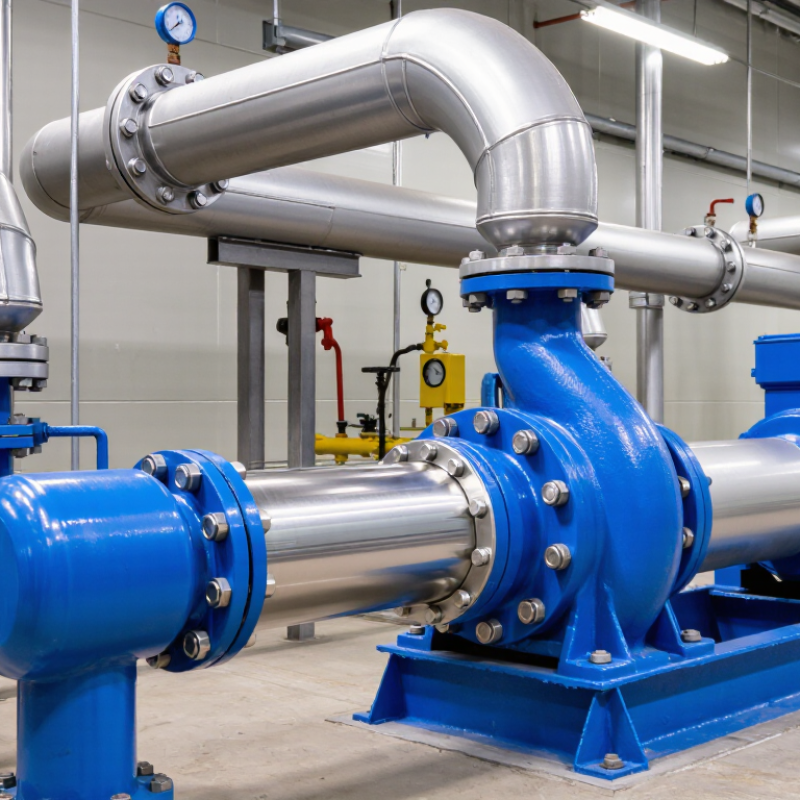
ISO pumps are usually standardized centrifugal pumps used for transferring water, chemicals, oils, and other process fluids. Their dimensions and performance requirements follow recognized ISO standards, supporting easier selection and maintenance. The main components include the casing, impeller, shaft, mechanical seal, bearings, coupling, motor, and baseplate. Each part has a specific job.
The motor rotates the shaft through the coupling. The shaft turns the impeller inside the casing. As fluid enters the impeller eye, rotating blades increase its velocity. The casing then converts much of that velocity into pressure. Fluid leaves through the discharge nozzle. The mechanical seal limits leakage around the rotating shaft. Bearings maintain alignment and reduce friction. A rigid baseplate supports the complete assembly. Wear rings may also control internal clearance and improve efficiency. Small clearances matter. Excessive wear can reduce flow and increase power consumption. In practical maintenance, vibration often reveals alignment problems before visible damage appears. However, vibration alone does not identify the exact cause. Suction blockage, cavitation, or bearing damage can produce similar symptoms.
Tips: Check the suction line before blaming the pump. Keep the inlet fully flooded when required. Inspect seal leakage, coupling alignment, and bearing temperature regularly. Record readings over time. One measurement can mislead. Avoid running the pump dry, even briefly, because the seal may overheat quickly. Always verify materials and operating limits against the fluid and service conditions.
ISO pumps are standardized centrifugal pumps commonly built around ISO 2858 dimensions. An impeller spins inside a casing, converting motor energy into fluid pressure and flow. Their standardized dimensions can simplify replacement and maintenance. However, “standardized” does not mean universally suitable.
These pumps serve chemical processing, water treatment, food production, cooling circuits, and general industrial transfer. Selection starts with duty conditions, not the pump name. Engineers define flow rate, total head, liquid temperature, viscosity, density, and vapor pressure. Corrosive liquids may require stainless steel or engineered alloys. Solids can demand an open impeller or wider passages. Mechanical seals also need careful review. A small mismatch may cause leakage, vibration, or premature wear.
Energy deserves attention. The U.S. Department of Energy’s Improving Pumping System Performance sourcebook reports that pumping systems can consume 25–50% of industrial facility energy in some applications. The right pump therefore operates near its best efficiency point, rather than simply delivering maximum capacity. Hydraulic Institute guidance also emphasizes checking NPSH margin and system resistance. Field measurements matter. A neat specification sheet can still describe the wrong operating reality. I would verify pressure readings, pipe losses, control-valve behavior, and seasonal demand before approval. Oversizing remains common, and throttling away excess flow is rarely a thoughtful design choice.