Sealless Pumps for a Safer and Greener World

Choosing a Hydraulic Piling Rig is a ground-and-project decision, not a horsepower contest. The right machine must match the pile type, required depth, soil conditions, site access, and working space. On a muddy site, track width and ground pressure can matter as much as rated torque. In a narrow urban lot, mast height and transport dimensions may decide whether the rig can reach the work area at all.
A practical rule is: “Match the rig to the ground, the pile, and the access—not just the specification sheet.” No source quotation or expert name was provided, so I can’t reliably attribute that sentence to a real industry specialist. The guidance remains simple, but the choice rarely is. A rig that performs well in dense gravel may struggle in soft clay or near buried obstructions. Review the site investigation, pile design, daily production target, available attachments, and maintenance support before comparing models.
This guide explains how to weigh those factors without treating a brochure figure as a guarantee. It also considers operator visibility, setup time, and service access—details that can be easy to overlook during procurement. Some trade-offs will remain. That deserves a second look.
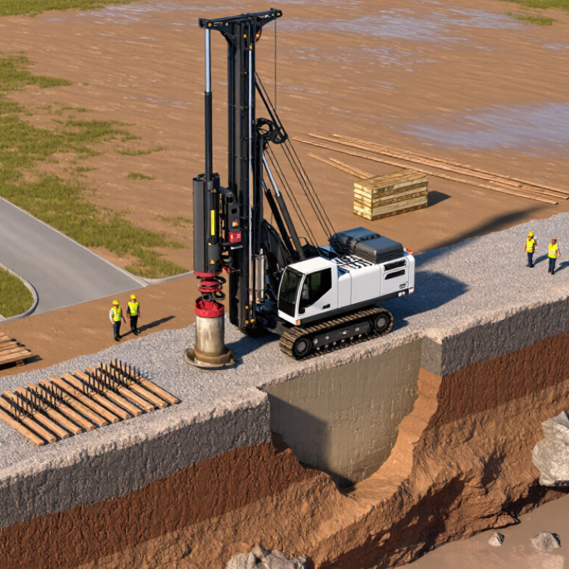
Choosing a hydraulic piling rig starts with the geotechnical design, not the machine catalogue. Identify the specified pile type, such as precast concrete, steel, or bored piles, and confirm the installation method. Soil conditions can change what works: dense gravel, soft clay, and shallow groundwater place different demands on equipment. Small details matter. Check the report’s soil layers, groundwater observations, and design assumptions before comparing rigs.
Next, match pile diameter and required depth to the rig’s operating range. The rig must handle the pile dimensions and provide suitable pressing force, torque, or drilling capacity for the chosen method. Confirm working height, leader stroke, and available clearance against actual site constraints. A pile that fits on paper may still be difficult to position beside an excavation or under overhead services. Reports can leave uncertainty, especially where investigation points are widely spaced. Flag those gaps with the geotechnical engineer rather than guessing. The final selection should reflect design loads, installation tolerances, access, and verified ground conditions. A short site review can expose a mismatch before equipment arrives.
How to Choose the Right Hydraulic Piling Rig?
Match rated torque and crowd force to the ground, not just the planned pile diameter. Torque turns the tool through resistant soil; crowd force pushes it downward and helps maintain penetration. In loose sand, excessive crowd can cause sudden advance and spoil control problems. Dense gravel or cemented layers may demand more torque, but higher torque alone will not solve poor tooling or an unsuitable drilling method. Not enough.
FHWA’s Design and Construction of Continuous Flight Auger Piles (FHWA-HIF-07-03, 2007) describes typical pile diameters of about 12–36 inches. That wide range is a useful scale check, not a rig-selection chart: diameter, depth, soil layering, and tooling all affect required torque and crowd. Compare the rig’s rated values at its actual operating speed, then check them against bore logs and trial-pile observations. A rig can meet its torque rating on paper yet struggle when dense gravel sits beneath soft clay.
Watch the spoil and penetration rate. If the auger stalls, the motor labors, or penetration becomes erratic, pause and reassess the ground and tool. FHWA’s manual emphasizes site-specific design and construction controls; use that principle alongside geotechnical records and, where appropriate, load-test evidence. Leave a margin for harder-than-expected layers. The exact margin is a judgment call, and that is worth documenting.
Check drilling diameter, maximum depth, and mast reach against pile plans
Start with the pile schedule, not the rig brochure. Record each pile’s diameter, toe elevation, and working-platform level. FHWA’s 2018 Drilled Shafts manual discusses shaft diameters of roughly 0.6 to 3.0 metres, showing how widely project requirements can vary. That range is not a rig-selection rule. It is a useful reminder to check the full diameter range on your plans, including any larger lead holes or casing requirements. A rig that handles the largest pile may not drill smaller piles efficiently.
Compare required depth with the rig’s usable drilling depth, not just its advertised maximum. Tool length, Kelly bar stroke, casing, and ground conditions can reduce practical reach. Check mast reach against platform elevations and overhead clearance, too. A mast may fit at ground level but foul a beam when the rig sits on a raised platform. Leave margin. It is easy to over-trust a single depth figure; I would verify the proposed setup against the deepest pile and the tightest access point. Put those checks on a pile-by-pile schedule. Small differences in elevation can matter.
Power and pressure describe different limits. Hydraulic output power can be estimated as pressure in MPa multiplied by flow in L/min, then divided by 60. At 25 MPa and 120 L/min, that equals about 50 kW before losses. Compare usable hydraulic power, not just engine rating. A high pressure figure alone may look impressive, but insufficient flow can slow the crowd cylinder or rotary head. Check continuous working pressure against peak pressure, too. Peaks are not a sensible daily operating target. The U.S. Department of Energy’s 2006 Improving Pumping System Performance sourcebook reports 20–50% energy-saving potential from optimizing industrial pumping systems; that broad figure is not a piling-rig guarantee, but it shows why wasted flow and throttling matter.
Duty cycle reveals whether the rig can sustain the work. Record loaded minutes, idle time, and pressure spikes across a real shift, including pauses for rod changes and repositioning. A rig rated at 60 kW may behave very differently when it runs continuously than when it works in short bursts. Watch hydraulic oil temperature and recovery time between cycles. The FHWA’s Design and Construction of Driven Pile Foundations (2016) emphasizes measured installation response and field records; apply the same discipline when comparing rig logs, while accounting for different piling methods. A neat spreadsheet can still miss a hot afternoon or stubborn ground. That is worth admitting. Ask for test data under comparable soil, tooling, and cycle conditions, then compare output per hour alongside fuel use.
Compare hydraulic power, system pressure, and duty cycle to match a rig to the pile, ground conditions, and planned workload.
Indicative screening ranges: compact 30–60 kW, mid-size 75–150 kW, heavy-duty 150–300 kW.
Indicative ranges: compact 20–28 MPa, mid-size 25–32 MPa, heavy-duty 28–35 MPa. Confirm the required pressure for the attachment.
Planning examples, not rig ratings: hydraulic-on time as a share of an 8-hour shift. Actual duty depends on the job and operating method.
How to use this chart: Treat the power and pressure bands as general screening guidance, not universal specifications. Compare manufacturer data for the complete rig and attachment, then check whether the machine is rated for your expected workload. Duty cycle is application-dependent and is not directly comparable as a single standard rig specification.
Verify capacity using ASTM D1143/D1143M static or ASTM D4945 dynamic tests
A rig’s rated force is not proof that a pile will meet its design capacity. Ground layers, pile length, installation energy, and setup after driving all affect resistance. ASTM D1143/D1143M provides procedures for static axial compression testing, while ASTM D4945 covers high-strain dynamic testing. The Federal Highway Administration’s 2016 driven-pile guidance describes static tests commonly loading piles to as much as 200% of design load. That figure is a test level, not an automatic acceptance criterion. The project engineer must define the required capacity and interpretation method.
Static testing applies measured loads and records pile movement over time. It can reveal settlement behavior directly, but needs reaction equipment and careful site planning. Dynamic testing measures force and velocity near the pile head during impact. It can provide rapid estimates, though results depend on signal quality and analysis assumptions. Check that the chosen rig can install the test pile under actual soil conditions, then verify capacity using the specified test method. For dynamic results, compare estimates with static data when available. A noisy signal or uncertain soil model can distort the answer.
One detail is easy to overlook: a rig that reaches the target depth may still leave the capacity question unresolved.



