Sealless Pumps for a Safer and Greener World

Choosing a 4 Pin Female Connector is rarely a simple matter of matching four terminals. The correct part must suit current, voltage, signal type, temperature, vibration, sealing, and installation space. A connector that fits the housing can still fail electrically or mechanically. That is not enough.
Industry demand explains why this decision deserves careful attention. MarketsandMarkets’ Connector Market report projects continued growth in the global connector industry through 2028, driven by vehicles, industrial automation, communications, and consumer electronics. Bishop & Associates also identifies automotive, transportation, and data-related equipment as major connector markets. These figures suggest more design choices, but they also create more opportunities for specification mistakes.
A practical selection process should begin with the application environment. Check the manufacturer’s rated current, contact resistance, insulation resistance, and operating temperature. Then compare mating cycles, wire gauge range, locking design, and terminal plating. In a dusty machine cabinet, an IP-rated housing may matter more than a low purchase price. In a vibrating vehicle harness, secondary locks and strain relief deserve close inspection. IEC 60529 can guide enclosure protection claims, while IPC/WHMA-A-620 supports workmanship expectations for cable and wire-harness assemblies. UL recognition may also help when approval requirements apply.
Small errors matter. A connector chosen only by appearance may overheat, loosen, or admit moisture. Product drawings can also omit real installation constraints, so confirm samples and perform fit, pull, and temperature checks before approval. Datasheets are essential, yet they are not the whole answer. The best 4 Pin Female Connector balances electrical performance, mechanical reliability, compliance needs, sourcing stability, and the realities of field service.
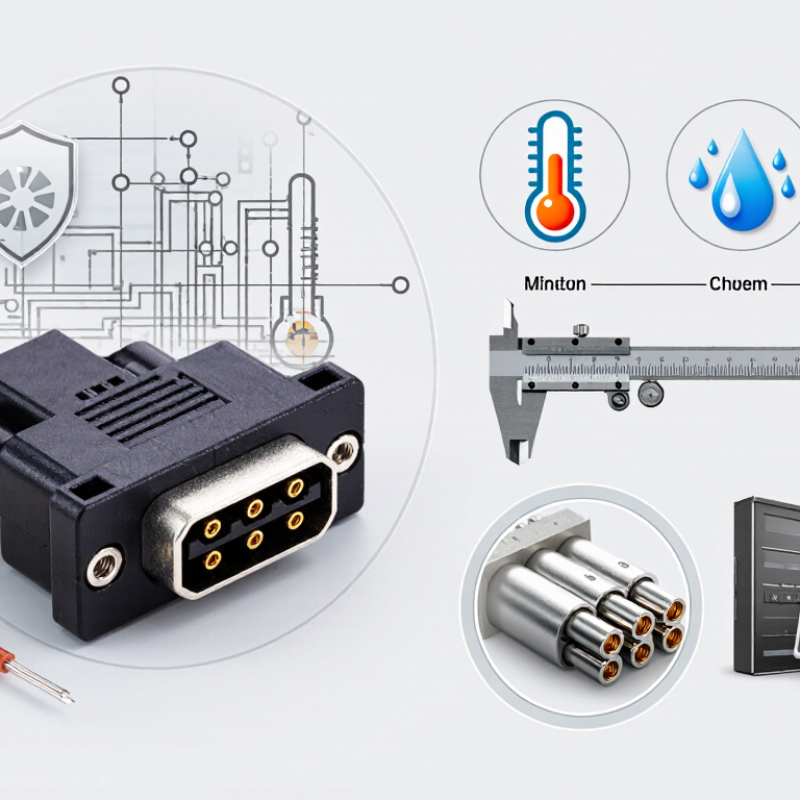
How to Choose the Right 4 Pin Female Connector?
A 4-pin female connector is not defined by pin count alone. Inspect the contacts first. Copper alloys provide good conductivity and spring strength. Gold plating helps resist oxidation in low-level signal circuits. Tin plating can suit cost-sensitive power connections. Check the rated current, voltage, and contact resistance. These figures should match the cable and load, not just the connector housing.
Pitch means the center-to-center distance between adjacent contacts. A smaller pitch saves space but leaves less room for assembly errors. Measure the mating connector with calipers before ordering. A one-millimeter mistake can stop the connection completely. Also examine the keying and coding features. A visible notch, guide rib, or keyed shape prevents reversed insertion. It can also stop two similar circuits from being mixed.
Standards deserve careful attention. Depending on the connector type, relevant requirements may include the IEC 61076 series, UL recognition, or equipment-specific safety rules. Do not assume a familiar shape meets every standard. In bench testing, I once selected the correct pitch but ignored cable-bend space. The contacts worked, yet the housing cracked during repeated movement. That mistake changed my selection process. Review mating cycles, sealing level, temperature range, wire size, and locking force. Small details matter.
4-Pin Female Connector Basics: A four-contact connector has three equal pitch intervals between the first and fourth contact centers. The chart compares common contact pitches and the resulting center-to-center span.
Selection guide: Confirm the required contact count, measure the pitch in millimeters, match the housing keying or coding, and verify the applicable safety and performance requirements, such as insulation spacing, current rating, voltage rating, and environmental protection.
How to Choose the Right 4 Pin Female Connector?
Start by defining the electrical load, not the connector shape. Record the working voltage, continuous current, peak current, and duty cycle for each of the four contacts. IEC 61984 helps frame connector safety, rated values, insulation, and protection requirements. However, its rating does not automatically fit every installation. A connector marked for 5 A may require derating when all four contacts carry current together.
Check the manufacturer’s technical data carefully. Compare the declared IEC voltage and current ratings with the circuit’s worst-case conditions. Review temperature limits, contact resistance, wire size, and mating cycles. UL connector ratings provide another useful reference, especially for recognized current, voltage, temperature, and flammability conditions. Do not treat a UL marking as a universal approval for the complete assembly. The housing, terminals, cable, and crimp process still matter.
Measure the real environment. A cabinet at 25°C differs from a motor enclosure reaching 70°C. Moisture, vibration, dust, and limited airflow can reduce practical performance. Clearance and creepage distances deserve attention when voltage rises. Small errors here can become expensive.
Leave margin.
A common selection mistake is using the maximum catalog current without checking heat buildup. I have seen compact four-contact designs pass a bench test, then show warmer terminals during continuous operation. That result deserves a second review, not confidence. Confirm the final configuration against the applicable IEC and UL documentation, installation method, and local certification requirements.
Choosing a 4 Pin Female Connector starts with the wire, not the housing shape. Confirm the conductor’s AWG, insulation diameter, and actual load current. A connector rated for 24 AWG may not accept thicker 20 AWG cable. IPC/WHMA-A-620 emphasizes controlled crimp height, insulation support, and pull-force verification. In practice, a loose crimp can create heat before failure becomes visible.
Contact resistance deserves equal attention. For low-voltage circuits, even 20 milliohms can matter. At 5 amperes, that resistance produces 0.5 watts at one contact. Measure mated resistance under the method described in IEC 60512-2-1, rather than trusting catalog claims alone. Test new parts and after repeated mating cycles. That detail is often skipped.
Temperature derating connects every decision. A connector rated at 105°C still loses thermal margin inside a 70°C enclosure. Add contact heating, nearby cable bundles, and poor airflow. IEC 60512-5-2 provides methods for current-carrying capacity evaluation, while IEC 60664-1 supports insulation coordination and temperature considerations. Use the manufacturer’s derating curve, not a single headline current value. For example, a 6-ampere rating at 25°C may fall sharply at 85°C. The exact reduction depends on contact spacing and wire gauge. My own design reviews have caught this mistake more than once. A clean table can still be wrong. Build a prototype, load all four circuits simultaneously, and record terminal temperature after thermal stabilization.
| Wire Size (AWG) | Conductor Area (mm²) | Typical Continuous Current Screening Range per Contact | Recommended Contact Resistance (Initial Maximum) | Typical Cable Flexibility | Suitable Application Examples | Main Selection Caution |
|---|---|---|---|---|---|---|
| 28 | 0.08 | Up to 1.0 A | ≤ 30 mΩ | Very high | Signal, sensor, encoder, and low-power control wiring | Small conductors have limited current and mechanical strength; verify crimp compatibility. |
| 26 | 0.13 | 1.0–2.0 A | ≤ 25 mΩ | High | Low-voltage electronics, instrumentation, and compact control harnesses | Allow for voltage drop when the cable is long or the load is sensitive. |
| 24 | 0.20 | 2.0–3.0 A | ≤ 20 mΩ | High | LED modules, communication equipment, and small actuators | Check the connector terminal's approved wire range rather than selecting by AWG alone. |
| 22 | 0.33 | 3.0–5.0 A | ≤ 15 mΩ | Medium-high | Industrial sensors, small motors, relays, and power-control circuits | Terminal heating can increase rapidly when several contacts carry current simultaneously. |
| 20 | 0.52 | 5.0–7.0 A | ≤ 15 mΩ | Medium | Compact power distribution, valves, fans, and moderate-current equipment | Confirm housing cavity size, crimp tooling, insulation diameter, and locking strength. |
| 18 | 0.82 | 7.0–10.0 A | ≤ 10 mΩ | Medium-low | Higher-current DC loads, compact motors, lighting, and power harnesses | Use only when the 4-pin connector is specifically rated for the conductor size and current. |
| Ambient Temperature | Suggested Design Current Factor* | What to Verify | Design Guidance |
|---|---|---|---|
| ≤ 30°C | 100% | Initial contact resistance, terminal fit, and connector current rating | Use the manufacturer's published rating only when test conditions match the application. |
| 31–60°C | Approximately 80% | Heat from adjacent contacts, enclosure ventilation, and cable bundle size | Reduce current or select a connector with a higher temperature rating. |
| 61–85°C | Approximately 50% | Housing material, terminal plating, seal rating, and long-term resistance stability | Perform a thermal test under the actual number of loaded contacts. |
| > 85°C | Application-specific | Connector temperature class, insulation temperature rating, and derating curve | Do not extrapolate a standard rating; obtain a validated derating curve or test result. |
*Important: The current ranges and derating factors are preliminary screening values for copper conductors and compact 4-pin connector selection. Actual allowable current depends on terminal geometry, contact spacing, number of simultaneously loaded contacts, conductor insulation, ambient conditions, duty cycle, connector orientation, and the applicable safety standard. Always use the final connector manufacturer's test data for product qualification.
For a 4 pin female connector, IP protection should match the actual installation environment. IEC 60529 separates protection into two digits. The first measures solid-particle protection, while the second measures water resistance.
IP54 handles dust-limited entry and water splashes.
IP65 adds protection against water jets.
IP67 supports temporary immersion, commonly up to one metre for 30 minutes.
IP68 allows deeper or longer immersion, but the manufacturer must define those conditions.
A connector installed inside a dry control cabinet may only need IP54. Outdoor machinery often requires IP65, especially near washdown areas. Submerged sensors need IP67 or IP68, plus a verified cable seal. IP68 is not automatically better. It can add cost, tighter assembly requirements, and harder field replacement.
A 2024 industrial-connectors market report projects approximately 6% annual growth through 2029, driven by automation, transport, and energy equipment. That growth reflects tougher operating environments, not a reason to over-specify every connector.
Check the mated condition, not only the connector shell. An uncapped socket can lose its rating. Cable diameter, locking force, vibration, temperature, and repeated mating also matter. IEC 60529 does not fully measure corrosion resistance or chemical exposure.
Field reviews often reveal a basic mistake: teams test water resistance before confirming seal compression. This order should change. Select the rating after identifying the water source, immersion time, and maintenance routine. Then verify test evidence, installation instructions, and the exact IP68 limits.
Choosing a 4 pin female connector starts with its real operating duty, not its appearance. Confirm the mating-cycle rating under the supplier’s stated test conditions. IEC 60512-9-1 covers mechanical operation tests, but cycle ratings can change with speed, load, alignment, and contamination. A connector rated for 50 cycles may not suit equipment serviced every week. Count expected insertions over the product’s life, then add a practical margin.
Check the housing material’s UL 94 classification. V-0 requires each flame application to produce no more than 10 seconds of afterflame, with a maximum total afterflame time of 50 seconds for five specimens, according to UL 94. V-1 and V-2 allow longer or less favorable burning behavior. This rating concerns material flammability, not complete assembly safety. Nearby insulation, wire size, and enclosure ventilation still matter. Do not treat V-0 as a universal approval.
Mechanical compatibility needs a physical check. Measure pitch, keying, latch position, contact spacing, wire exit direction, and panel clearance. IEC 60512 test methods address connector dimensions, retention, and mechanical performance. Match the connector to the correct wire gauge and current rating. A tight latch can still fail if the plug bottoms out before full contact engagement. Small details matter.
A simple sample fit test helps. Inspect five mating cycles by hand, then repeat with slight vibration or cable pull. Look for looseness, uneven force, and terminal back-out. Specifications can seem precise, yet installation errors remain unpredictable. That is where many selections need rethinking. (UL 94; IEC 60512)



