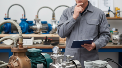
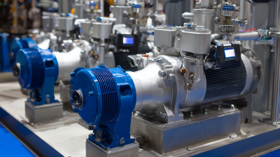
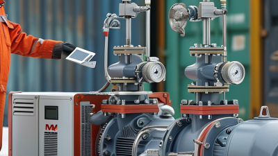
Sealless Pumps for a Safer and Greener World

Fluid pumps move liquids by adding mechanical energy to a fluid. They appear in water networks, chemical plants, oil refineries, hospitals, and household appliances. Some are compact enough to fit in one hand. Others fill entire rooms with steel, valves, motors, and control panels.
The basic principle is simple. A driver turns an impeller, rotor, piston, or diaphragm. That motion creates pressure, flow, or both. Centrifugal pumps accelerate liquid outward, while positive-displacement pumps trap and push measured volumes. The real answer is less tidy. Performance changes with viscosity, temperature, pipe resistance, air entrainment, and maintenance quality.
Pump engineer and author Lev Nelik defines a pump as “a machine that adds energy to a fluid” in Centrifugal and Rotary Pumps: Fundamentals with Applications. That short sentence captures the central idea. It does not explain every failure.
The U.S. Department of Energy’s Pumping System Sourcebook reports that pumping systems can represent about 27% of electricity use in U.S. manufacturing. The same guidance highlights major savings from correctly sized pumps, efficient controls, and reduced system resistance. Hydraulic Institute’s Pump Life Cycle Costs guide also stresses that purchase price is only one part of ownership cost.
Energy matters.
A pump can run quietly while wasting power through throttled valves, oversized motors, or worn components. Engineers therefore evaluate head, flow rate, efficiency, net positive suction head, and life-cycle cost together. These measurements turn a vague machine into a system that can be tested and improved.
This article explains what fluid pumps are, how their main types work, and why real-world design rarely follows a perfect diagram.
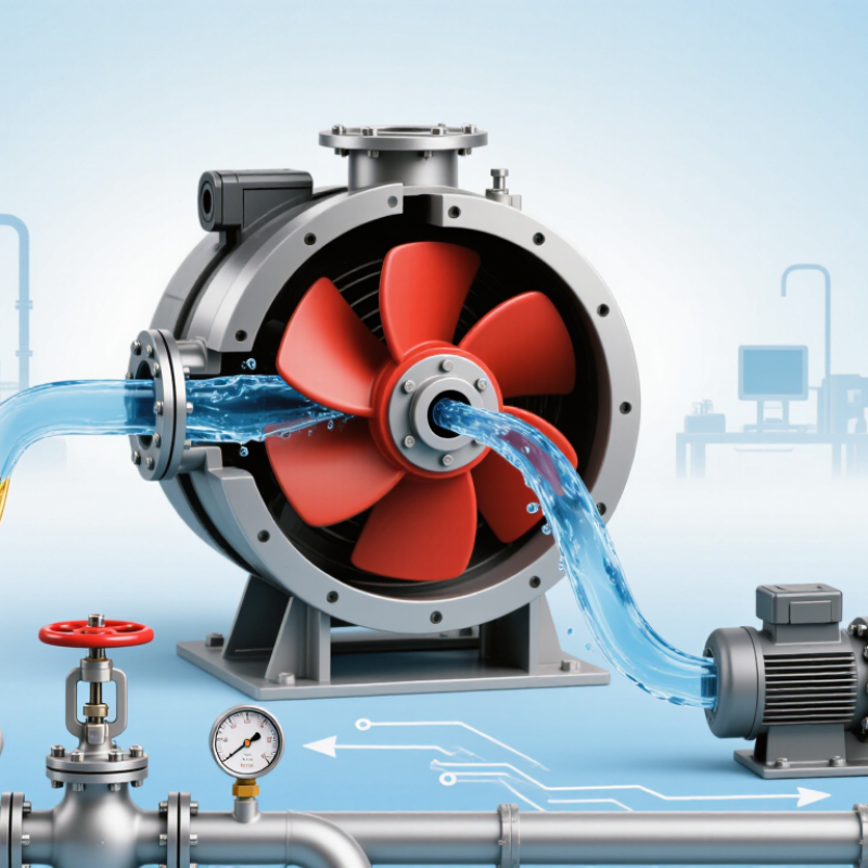
Fluid pumps are machines that move liquids or gases through a system. They create flow by adding pressure or changing volume inside a chamber. A pump does not make fluid disappear; it gives the fluid enough energy to travel. Water, oil, fuel, chemicals, slurry, and wastewater are common materials transported by pumps. Some pumps also handle air or other gases. The choice depends on viscosity, temperature, pressure, and particle size.
In practical systems, centrifugal pumps use rotating impellers to push fluid outward. Positive-displacement pumps trap a measured volume and force it forward. This difference matters. A thin liquid may flow easily through narrow pipes, while thick syrup needs stronger, slower movement.
Pumps can transfer liquid between tanks, feed boilers, circulate cooling water, or remove floodwater. However, a pump can fail when the inlet is blocked, the fluid contains unexpected solids, or the pressure is poorly matched. I have seen diagrams make pumping look simple. Real installations are less forgiving.
Tips: Check the fluid’s temperature and viscosity before selecting a pump. Measure pipe length, elevation, and required flow rate. Install a suitable filter when particles may enter. Listen for rattling or irregular vibration; these signs may indicate air, wear, or cavitation. Keep a maintenance record, even when the equipment seems quiet.
A fluid pump is a compact energy system, not merely a motor with pipes attached. Its casing guides the liquid and contains pressure. Inside, the impeller spins in a centrifugal pump, adding velocity to the fluid. A positive-displacement pump uses gears, screws, pistons, or diaphragms instead. The design changes, but the purpose remains controlled movement.
The shaft transfers torque from the motor to the rotating element. Bearings keep that shaft aligned under load. Mechanical seals or packing reduce leakage around the shaft, although neither solution is perfect. Suction and discharge ports direct flow through the casing. Check valves can prevent reverse flow, while pressure and temperature sensors reveal problems before failure. Small details matter. A worn seal may waste fluid gradually. A misaligned shaft can create heat, vibration, and premature bearing damage.
The U.S. Department of Energy’s Pumping System Sourcebook reports that pumping systems may represent 25% to 50% of industrial energy use in some facilities. This makes component selection an operating-cost decision, not only an engineering detail. DOE guidance also recommends evaluating the complete system, including pipes, valves, controls, and demand patterns. That point is often overlooked. A highly efficient impeller cannot compensate for a blocked filter or an oversized motor. In field inspections, vibration readings and flow measurements usually tell a more honest story than a clean equipment drawing. Performance can drift. Regular inspection remains essential.
This chart compares representative working-pressure capabilities of common fluid-pump designs. Inside a pump, the casing or cylinder contains the fluid, the impeller, gears, diaphragm, or piston transfers energy to it, and valves, seals, bearings, and shafts control flow while preventing leakage. Pressure varies with pump size, speed, fluid properties, and operating conditions.
Fluid pumps move liquids from an inlet to an outlet by creating a pressure difference. A pump does not create flow from nothing. It adds energy to the fluid, allowing pressure to push liquid through pipes, valves, and equipment.
In a centrifugal pump, a rotating impeller accelerates liquid outward inside a casing. This increases pressure before the liquid reaches the outlet. At the inlet, lower pressure draws more liquid into the pump. Positive displacement pumps work differently. A piston, diaphragm, or gear traps a measured volume and pushes it forward. Their flow can remain steady against higher resistance, though pulsation may occur.
Small details affect real performance. A partially closed valve increases resistance and changes the flow rate. Air entering the suction line can cause noise, vibration, and uneven delivery. Low inlet pressure may create cavitation, where vapor bubbles form and collapse against internal surfaces. That damage is easy to overlook. Pipe size, liquid viscosity, temperature, and pump speed must match the application. Operators often check pressure gauges, listen for unusual sounds, and inspect seals for leaks. Measurements matter, but field conditions can still surprise us. A pump rated for a certain flow may deliver less when filters clog or long pipe runs add friction.
| Important Dimension | Centrifugal Pump | Rotary Gear Pump | Diaphragm Pump | Peristaltic Pump | Reciprocating Piston Pump |
|---|---|---|---|---|---|
| Operating Principle | Uses a rotating impeller to increase fluid velocity, then converts velocity into pressure through the casing. | Uses rotating gears to trap and carry fixed volumes of fluid from the inlet to the outlet. | Uses a flexible diaphragm that moves back and forth to create alternating suction and discharge strokes. | Uses rollers or shoes to compress flexible tubing and move fluid through a series of occluded sections. | Uses a piston or plunger moving inside a cylinder to draw in and discharge fluid through valves. |
| Typical Flow Behavior | Continuous flow with relatively low pulsation. | Positive-displacement flow; generally steady, with some pulsation depending on gear design and speed. | Pulsating flow caused by alternating suction and discharge cycles. | Low-shear, pulsating flow with accurate volume transfer at controlled speeds. | Strongly pulsating flow unless a dampener or multiple cylinders are used. |
| Common Flow Range | Approximately 1 to 10,000 m³/h, depending on pump size and configuration. | Approximately 0.01 to 500 m³/h, depending on displacement and operating speed. | Approximately 0.001 to 100 m³/h, depending on diaphragm size and drive system. | Approximately 0.0001 to 50 m³/h, with precise control at low flow rates. | Approximately 0.001 to 500 m³/h, depending on cylinder size, stroke length, and speed. |
| Typical Pressure Capability | Commonly up to 10 bar for general service; multistage designs can exceed 100 bar. | Commonly 5 to 25 bar, with specialized designs reaching higher pressures. | Commonly 2 to 20 bar, depending on diaphragm material and construction. | Commonly 2 to 15 bar; maximum pressure is often limited by tubing strength. | Commonly 50 to 1,000 bar or more in high-pressure applications. |
| Best Fluid Characteristics | Clean or lightly contaminated, low- to medium-viscosity liquids. | Lubricating liquids, oils, fuels, polymers, and other medium- to high-viscosity fluids. | Corrosive, abrasive, viscous, or solids-containing liquids when compatible materials are selected. | Sensitive, abrasive, shear-sensitive, or sterile fluids that must remain inside the tubing. | Clean or filtered liquids requiring high pressure and accurate metering. |
| Self-Priming Capability | Usually limited; many installations require a flooded inlet or priming arrangement. | Generally self-priming when the pump is properly sealed and operated within its limits. | Generally self-priming and capable of handling intermittent dry operation. | Generally self-priming and able to run dry for limited periods, depending on tubing material. | Often self-priming, although suction lift and valve design affect performance. |
| Main Advantages | Simple construction, smooth flow, compact size, and good efficiency for high-flow service. | Accurate displacement, good performance with viscous liquids, and broad speed control. | Good chemical resistance, leak-minimized operation, and suitability for solids or abrasive fluids. | Excellent fluid isolation, gentle handling, and easy maintenance through tubing replacement. | Very high pressure capability, accurate dosing, and strong performance at low flow rates. |
| Main Limitations | Performance decreases with very viscous fluids; operation can be damaged by cavitation or dry running. | Requires close internal clearances; abrasive particles can accelerate wear and reduce volumetric efficiency. | Flow pulsation, diaphragm fatigue, and limited output at very high flow rates. | Tubing fatigue, pulsating flow, and pressure limitations imposed by the hose or tube. | More complex construction, higher maintenance requirements, and significant pressure pulsation. |
| Typical Applications | Water circulation, cooling systems, irrigation, drainage, and general process transfer. | Lubrication systems, fuel transfer, chemical dosing, polymer handling, and oil circulation. | Wastewater treatment, chemical transfer, paint handling, slurry movement, and pneumatic process systems. | Laboratory dosing, medical equipment, food processing, wastewater treatment, and chemical metering. | High-pressure cleaning, hydraulic systems, injection service, pressure testing, and precision dosing. |
| Key Inlet-to-Outlet Action | Impeller energy raises fluid velocity; the casing converts that velocity into discharge pressure. | Expanding cavities at the inlet create suction, while decreasing cavities force fluid toward the outlet. | Diaphragm movement lowers inlet pressure during suction and raises outlet pressure during discharge. | Moving compression points push discrete fluid volumes forward while preventing backflow. | Piston retraction creates suction through the inlet valve; the forward stroke opens the outlet valve. |
| Typical flow and pressure ranges are broad engineering reference values. Actual performance depends on fluid viscosity, temperature, density, solids content, inlet conditions, pump size, speed, materials, and system resistance. | |||||
What Are Fluid Pumps and How Do They Work?
Fluid pumps move liquids through pipes, filters, valves, and processing equipment. Their operating method depends on pressure, flow rate, fluid thickness, and temperature. Centrifugal pumps use a spinning impeller to accelerate liquid outward. The casing then converts that velocity into pressure. They suit clean water and other low-viscosity fluids with steady flow requirements.
Positive displacement pumps work differently. They trap a fixed volume and push it forward during each cycle. Gear, piston, screw, diaphragm, and peristaltic pumps belong to this group. They handle thicker liquids and can produce accurate flow at lower speeds. A diaphragm pump uses a flexible membrane, while a peristaltic pump squeezes flexible tubing. These designs reduce direct contact between moving parts and the fluid. However, every method has trade-offs. A centrifugal pump may lose performance when air enters the line. A positive displacement pump may suffer damage if its outlet becomes blocked. Field experience shows that “stronger” is not always better.
Tips: Check the fluid’s viscosity before choosing a pump. Confirm the required flow and pressure together. Install a filter when particles could damage internal parts. Watch for unusual noise, vibration, leaks, or heat. Small warning signs matter. Read the pump curve, and leave room for changing conditions. A careful operator should question assumptions, because real systems rarely behave exactly like the original design.
What Are Fluid Pumps and How Do They Work?
Key Factors That Affect Pump Performance and Selection
Fluid pumps move liquids by adding mechanical energy to the flow. An impeller, piston, or diaphragm creates pressure, while piping directs the liquid. The pump does not produce flow alone. Its duty depends on system resistance, valve position, and elevation. A useful selection begins with the required flow rate and total dynamic head. These values define the operating point. For example, a cooling-water pump may need 40 m³/h against 28 meters of head. Guesswork here can cause noise, overheating, or poor circulation.
Fluid properties strongly affect performance. Viscosity changes power demand and may reduce flow through small passages. Temperature can lower viscosity, increase vapor pressure, and weaken seals. Solids require suitable clearances and wear-resistant wetted parts. Corrosive liquids demand compatible materials, not merely thicker metal. Net positive suction head available must exceed the pump’s requirement. Otherwise, vapor bubbles may collapse inside the impeller and damage surfaces. This is cavitation. It often sounds like gravel.
Efficiency matters, but the highest rated efficiency is not always the best choice. A pump operating far from its best efficiency point may vibrate and consume excessive power. Variable-speed control can match changing demand, though frequent cycling may create new stresses. Check motor capacity, start-up conditions, pipe diameter, and maintenance access. Field measurements can challenge design calculations. A spreadsheet may ignore a clogged strainer or sharp elbow. That is where selection becomes less certain. Record pressure, flow, temperature, and vibration after installation, then adjust the judgment.